Roundabouts
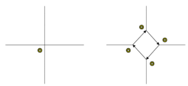
Roundabouts are a form of unsignalized intersection in which traffic circulates around a one-way closed lane to travel from an approach to an exit. Traffic on an approach must give way to traffic which is already on the circulating section. There are no constraints on traffic leaving the roundabout.
The circulating flow past an entry is the only flow which influences the capacity of that entry. The model builder, therefore, can always represent the circulating lane explicitly in the network, without compromising the modeling of the intersection. Individual roundabout models are placed at each entry. The approach characteristics of the actual roundabout entries remain unchanged. One of the circulating legs is exit only and the other circulating leg should be coded so that vehicles entering the roundabout from that approach are not significantly constrained. This technique is particularly useful for modeling roundabouts with five or more legs.
CUBE Voyager offers two ways to model roundabouts:
-
Gap-acceptance model — Each entry is characterized by a critical gap and a follow-up time. CUBE Voyager supports both HCM 2000 and HCM 2010 roundabout models. This setting is controlled by the HCMVERSION keyword.
-
Empirical model — Each entry is characterized by a capacity slope and a capacity intercept. The methodology is implemented based on the TRRL report 940.
Both models can be used to analyze the capacity, delay, queue and LOS of roundabout intersections. The low flow delay is the inverse of the capacity for roundabout intersections.
You can calculate the slope and intercept outside of CUBE Voyager, or you can supply geometric data and let CUBE Voyager calculate the slope and intercept using formulas calibrated in the UK.
Worldwide experience with roundabouts and roundabout models leads to the following conclusions:
-
When a well calibrated empirical model exists, it should be used in preference to a gap acceptance model.
-
However, the calibration of relationships between geometry, on one hand, and slope and intercept, on the other, requires very large amounts of data.
-
The number of roundabouts in the US is not yet sufficiently great to allow calibration of a US empirical model
-
Even when general countrywide empirical relationships exist, it may be necessary to fine tune the slope and intercept for local conditions.
-
When no general countrywide empirical relationships exist, it is better to use a gap acceptance model.
The Highway Capacity Manual (HCM 2000) indicates appropriate parameter ranges for a single-lane roundabout entry in the US.
References
-
Transportation Research Board. Highway Capacity Manual 2000.
-
Transportation Research Board. Highway Capacity Manual 2010.
-
Hollis, E. M., Semmens M. C. and Denniss S. L. (1980). ARCADY: A Computer Program to Model Capacities, Queues and Delays at Roundabouts. Transport and Road Research Laboratory Report RL 940.
Empirical roundabouts: Keywords
This section describes keywords to model empirical roundabouts:
Note: Keywords are case-insensitive. For example, capitalizing as ApproachWidth might improve readability.
This real-valued keyword allows the specification of the approach half width (in meters or feet), one of the geometric parameters for the U.K.-calibrated empirical roundabout model.
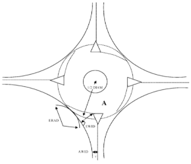
To measure the approach half width, measure from the road center line to the curb at a point sufficiently far from the roundabout that the curb and center line are parallel. In the diagram below, the double arrow marked "v" (below the arrow) and AWID (to the left of the arrow) illustrates the measurement.
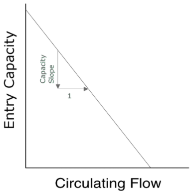
At an empirically modeled roundabout, each approach is characterized by two real numbers, the capacity slope and the capacity intercept. The capacity intercept is the entry capacity when the circulating flow is zero. The CAPACITYINTERCEPT keyword may be used to supply the capacity intercept directly.

If CAPACITYINTERCEPT is coded for a roundabout entry, CAPACITYSLOPE must also be coded for that entry and none of the roundabout geometric parameters may be coded for that entry.
At an empirically modeled roundabout, each approach is characterized by two real numbers, the capacity slope and the capacity intercept. The capacity slope is the marginal decrease in entry capacity when the circulating flow is increased by one PCU per hour. The CAPACITYSLOPE keyword may be used to supply the capacity slope directly.
If CAPACITYSLOPE is coded for a roundabout entry, CAPACITYINTERCEPT must also be coded for that entry and none of the roundabout geometric parameters may be coded for that entry.
This keyword specifies the position of a zebra crossing on an approach to a roundabout or a minor approach priority junction. Its value is the number of vehicles that may queue at the junction without impeding pedestrians who wish to cross. At roundabouts and single lane minor approaches to priority junctions, a single integer value should be supplied. However, on two-lane minor approaches to priority junctions, separate values should be supplied for each of the two lanes.
This integer-valued keyword specifies the position of a zebra crossing on an exit from a roundabout or priority junction. Its value is the number of vehicles that may queue at the crossing without impeding vehicles using other exits from the junction.
This real-valued keyword allows the specification of the length of a zebra crossing that crosses an approach to a roundabout or priority junction. If it is absent then no crossing will be modeled.
This real-valued keyword allows the entry angle, theta, of a roundabout to be coded.
There are three cases for the measurement of phi.
Case 1: A roundabout with straight weaving sections

-
Let A be the point where the entry line meets the inside edge of the lane.
-
Let D be the point on the median island (or line) of the following entry which is nearest to A.
-
EF is curve which is in the middle of the area of road for vehicles entering the junction.
-
BC is a tangent to EF at the point where EF intersects the stop line.
-
phi is the angle between BC and AD.
Case 2: A roundabout with long curved weaving sections
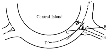
The construction for case 2 is nearly identical to that for case 1. However, the line AD is replaced by a curve A’D’ which is always parallel to the weaving section.
Case 3: A roundabout with short weaving sections

-
EF and BC are constructed as in case 1.
-
JK is constructed in the same way as EF, but for the following exit.
-
GH is the tangent to JK where JK meets the edge of the circulating section.
-
L is the intersection of BC and GH.
-
phi is zero or (90 - 1⁄2(angle GLB)), whichever is greater.
This real-valued keyword allows the specification of the entry radius (in meters or feet), one of the geometric parameters for the U.K.-calibrated empirical roundabout model.
The entry radius is defined as the minimum radius of curvature of the curb line at the entry.
This real-valued keyword allows the specification of the entry width (in meters or feet), one of the geometric parameters for the U.K.- calibrated empirical roundabout mode.
To measure the entry width:
-
Let A be the point where the stop-line meets the inside edge of the lane.
-
Let B be a point on the curb-line such that the line A-B is normal to the curb at B.
-
The entry width is the length of the line A-B.
In the diagram below, the double arrow marked C and "EWID" illustrates the measurement.
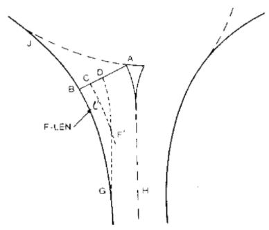
This real-valued keyword allows the specification of the modified flare length (in meters or feet) for the entry to an empirically modelled roundabout. This is measured using the following procedure:
-
Let A be the point where the stop line meets the inside edge of the lane.
-
Let B be the point on the curb line such that the line A-B is normal to the curb line at B (A-B is the entry width, e).
-
Let v be the approach width. Let D be a point on A-b such that the length of A-D is v.
-
Let D-G be a curve through D and parallel to the inside edge of the lane. (G is the point where the curve meets the curb).
-
Let C be the mid point of D-B.
-
Let C-F’ be a curve parallel to the curb which intersects the curve D-G at F’.
-
The modified flare length is the length of the curve C-F’.
This real-valued keyword allows the specification of the inscribed circle diameter of the roundabout (in meters or feet). Usually this is the largest circle that can be inscribed wholly within the outline of the junction (see figure below). However, when the intersection is very asymmetrical, a local value in the region of the entry should be taken.
Empirical roundabouts: Example
The following example uses geometrical data to calculate slopes and intercepts:
Junction,
  Node = 213,
  Type = Roundabout,
  Approach1 = 223,
  Approach = 223,
    EntryWidth = 12.5,
    ApproachWidth = 7.3,
    FlareLength = 25.0,
    InscribedDiameter = 25.0,
  Approach = 224,
    EntryWidth = 10.0,
    ApproachWidth = 6.0,
    FlareLength = 15.0,
    InscribedDiameter = 25.0,
  Approach = 321,
    EntryWidth = 10.0,
    ApproachWidth = 6.0,
    FlareLength = 15.0,
    InscribedDiameter = 25.0,
After comparing the model results to the performance of the intersection on the ground, it was decided to recode approach 224 to give the slope and intercept directly:
Junction,
  Node = 213,
  Type = Roundabout,
  Approach1 = 223,
  Approach = 223,
    CapacitySlope = 0.2,
    CapacityIntercept = 3600,
  Approach = 224,
    EntryWidth = 10.0,
    ApproachWidth = 6.0,
    FlareLength = 15.0,
    InscribedDiameter = 25.0,
  Approach = 321,
    EntryWidth = 10.0,
    ApproachWidth = 6.0,
    FlareLength = 15.0,
    InscribedDiameter = 25.0,
Gap acceptance roundabouts: Keywords
This section describes the keywords to model gap-acceptance roundabouts:
This keyword identifies how right-turn lanes yields at roundabout. This depends upon the existence of exclusive right-turn lanes on the subject link. Below is a screenshot from HCM 2010 Exhibit 21-8 that explains how this keyword is used. For the new calculators, the following values are used:
-
If RT=1, then BYPASSTYPE is non-yielding. Value=2 in Junction.
-
If RT, then BYPASSTYPE is default. Value=0 in Junction.
-
User needs to input the BYPASSTYPE for yielding lanes.

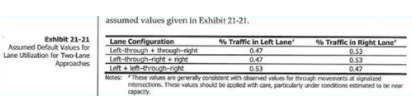
This keyword specifies the lane utilization factor of the left-turn of the approaching link. Exhibit 21-21 (see below) is used for reference. For the new calculators, the following values are used:
CIRCULATINGLANE**** specifies the number of circulating lanes in the roundabout. This is identified by comparing the cross street lanes. For each apporach, lanes at legs 2 and 4 (for a 4-link roundabout) or legs 2 and 3 (for a 3-link roundabout) will be obtained and the maxt of the values will be used. By default, CUBE Junction model will keep teh default value as 1 unless specified by user.
Keywords are case-insensitive but the recommended capitalization CriticalGap may improve readability.
The critical gap, in seconds, is one of the parameters of any gap- acceptance capacity model. At roundabouts, it is applicable by arm. It is defined as the minimum time interval in the circulating stream that allows intersection entry for one vehicle.
The U.S. Highway Capacity Manual 2000 suggests that, for a single- lane roundabout entry in the US, the critical gap should be in the range 4.1 to 4.6 seconds.
The follow-up time, in seconds, is one of the parameters of any gap- acceptance capacity model. At roundabouts, it is applicable by arm. It is defined as the time between the departure of one vehicle from the entry and the departure of the next vehicle using the same circulating flow gap, under a condition of continuous queuing on the entry.
The U.S. Highway Capacity Manual 2000 suggests that, for a single- lane roundabout entry in the America, the follow-up time should be in the range 2.6 to 3.1 seconds.
Gap acceptance roundabouts: Example
The following illustrates a gap-acceptance roundabout model:
Junction,
  Node = 253,
  Type = Roundabout,
    Approach1 = 32,
    Approach = 32, 208,
      CriticalGap = 4.6,
      FollowUpTime = 3.1,
    Approach = 256,
      CriticalGap = 4.35,
      FollowUpTime = 2.85,
    Approach = 486,
      CriticalGap = 4.1,
      FollowUpTime = 2.6,